Reducing unwanted radar reflections during calibration eliminates distortions and leads to more precise test signal readings, explains Pawel Wegrzyniak, technical lead at Laird Performance Materials.
The stakes have never been higher in achieving greater accuracy in ADAS calibration. Too often, precise testing of ADAS radar systems is hampered by a failure to adequately absorb incident signals that can arise in calibration environments. In roadway situations, false positive or false negative readings from radar sensors, the result of unwanted reflections or distorted signals, can lead to driver misjudgments and collisions. Calibration is critical for added driver safety and government compliance. The equipment used is increasingly sophisticated.
However, 77Ghz sensors are not perfectly stable due to higher frequencies and varying material parameters. This causes the antenna pattern to vary from sensor to sensor. To ensure angular measurement, each radar sensor must be calibrated according to a known reference reflector. OEMs, with support from their suppliers, need to calibrate the radar once integrated into the car structure to ensure that the radar will boost safety.
On the aftermarket side of things, repair shops and car dealers need technicians to understand innovative technologies and make accurate ADAS recalibrations. Equipment also must be designed with robust technologies – enabling aftermarket platforms to be equal to the equipment OEMs use for end-of-line calibrations. New radar designs must ensure that components work as desired under all conditions. This creates measurement tasks for calibration equipment. To reduce design uncertainty, test solutions are required.
Cycle time, automation, accuracy and reliability remain key. Automotive radar sensors are to be evaluated according to the ETSI EN 303 396 standard as a common base for test procedures, with a focus on ETSI EN 302 858 for 76-77Ghz and ETSI EN 302 264 for 77-81Ghz. Additionally, offering worthwhile guidance to designers as interim steps toward autonomy is the Safety for the Evaluation of Autonomous Products guide (UL4600).
Overall, Functional Safety Standard ISO 26262 and SOTIF compliance are key to understanding how to avoid liability. That includes requirements-based designs as well as adequate testing. Furthermore, radome is an important part of the sensor, both at the radar level as well as at integration into the car level. Testing equipment measuring the performance of these dielectric covers is vital in promoting overall radar functionality.
At the radar integration stage, radars are covered by radar domes constructed of material transparent to RF signals for cosmetic and protection purposes. The emblem on the grille is often used for this purpose. With increasingly higher frequency radars, those elements must be considered in the design. This can avoid any adverse effects on radar accuracy. A non-optimized radome causes reflection of RF signals and degrades radar performance.
Testing equipment within the radar supply chain
Radar testing units are required at multiple stages of the radar manufacturing and integration processes. Their purpose ranges from design phases to final quality checks.
Beyond standard measurement of azimuth angles, relevant testing requires measurement of reflectivity and transmission loss of the radome from the housing and/or placed in front of the radar sensor after mounting. While radar manufacturers test radome housings, OEMs calibrate the complete radar unit once mounted. This unit is often placed behind an aesthetic fascia (often the car emblem).
Reflectivity quantifies the energy that does not pass through the radome. Reflectivity degrades performance and impairs correct operation. The expected reflectivity depends on the sensitivity of the radar unit and the maximum required detection distance. Transmission loss describes the power level that is absorbed by the radome material. The higher the transmission loss, the lower the maximum radar range.
Radar unit evaluation
To evaluate a radar sensor realistically and reproducibly, numerous factors need to be considered. On the one hand, a radar sensor can be stimulated by generated radar echoes that correspond to real radar objects. Typical measurements include the different distances, relative speeds and azimuth angles. On the other hand, undesired radar reflections must be avoided. The radar test bench enables verification of the radar sensor and specific antenna diagram measurements.
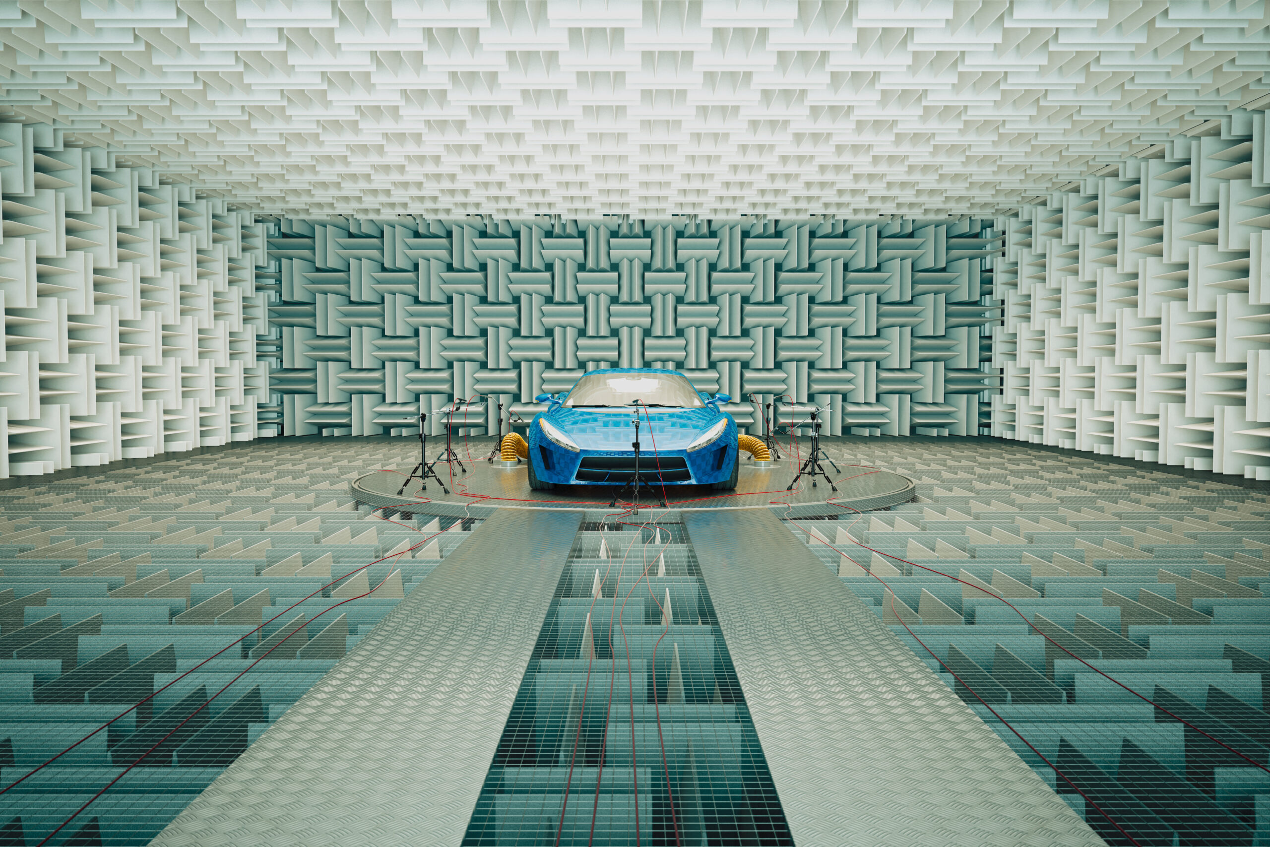
Most radar test benches use similar principles. To evaluate the entire chain of effects, the test bench provides over-the-air stimulation of the radar sensor front end. The test bench enables reliable multi-target angle simulation in real time. The test bench consists of an anechoic chamber with send/receive functionality. Test boxes are miniature anechoic chambers covered entirely with an absorber material to reduce or eliminate unwanted reflections.

For the test, the radar sensor is locked into the chamber where it is stimulated with radar echoes. The concentric movement of the antennas returns information on their azimuth angles. The simulation can include the front bumper and chassis. This way, all the software and hardware layers are part of the evaluation, from detecting the signal at the front of the radar to evaluating it in the radar’s ECU. The coherent echoes enable the radar ECU to reliably determine the distance and the velocity of the radar-detected objects. Driving scenarios can be simulated with the automotive simulation models. The radar test bench could support radar sensors with 24GHz, 77GHz and 79GHz of any modulation scheme.

Within OEM factories, final radar calibration is completed once the radar is integrated at the end of the assembly line. Bench tests are used in a reflection-free environment to maximize reliability.
Calibration equipment
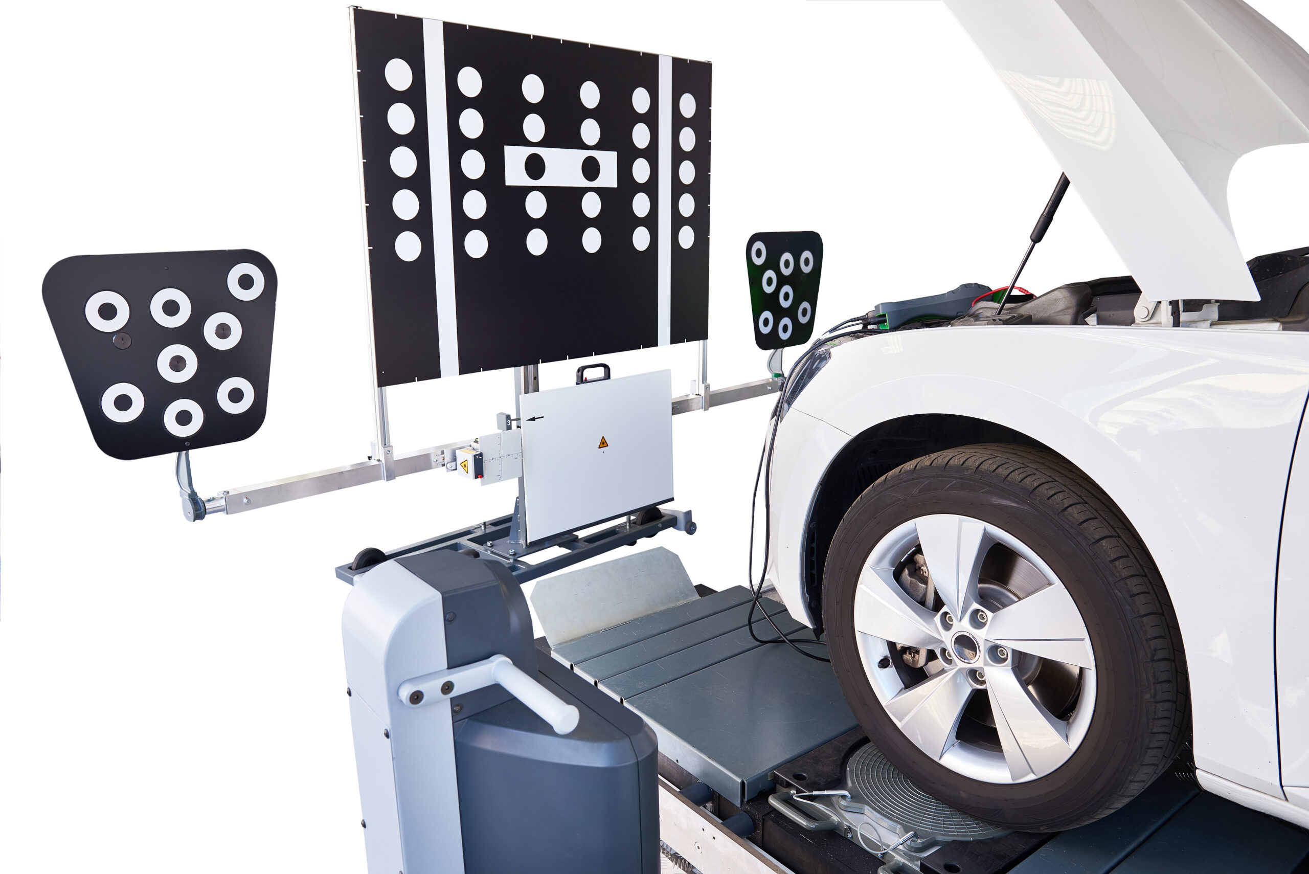
ADAS safety systems are advanced electronics, yet they often must be readjusted after accidents, window replacement, control unit replacement, adjustments in the vehicle chassis or inappropriate behaviors. Responding to this, manufacturers must guarantee that ADAS calibration equipment enables easy handling, compatibility and high reliability.
ADAS calibration equipment ideally functions flawlessly and ensures no external signals and unwanted reflections will lead to inaccurate signal readings. Consequently, fixed wall or mobile wall reflection protection – along with structural reflection coverage – must be ensured using absorber solutions which guarantee complete reliability.
One new solution: absorber surface-texturing technology
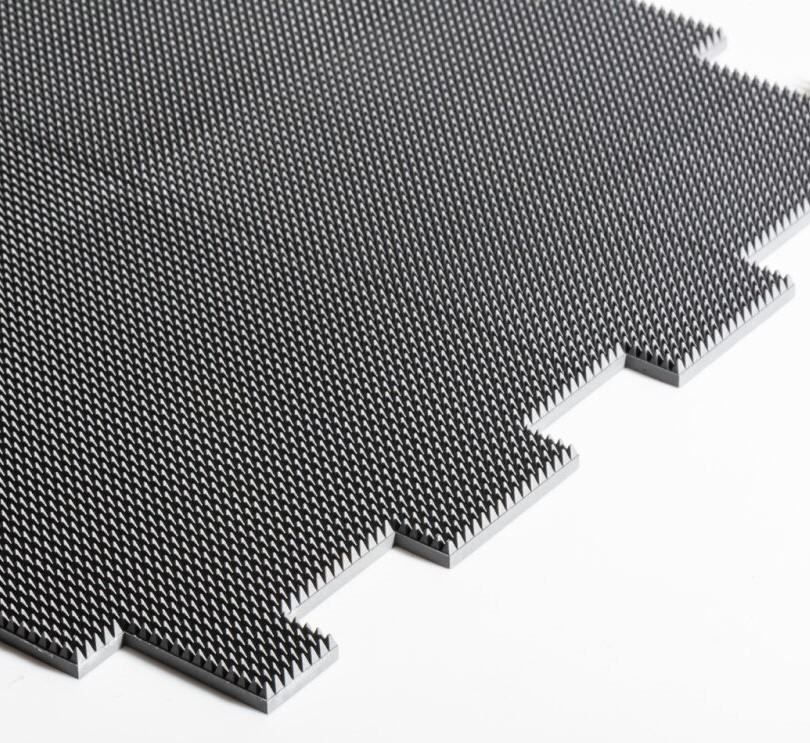
One answer is advanced absorbers featuring surface-texturing technology. They deliver maximum absorber reflectivity performance in the millimeter wave frequency band using a robust and environmentally friendly material.
Traditional absorber foam can lack advantages in demanding applications outside of a laboratory environment. Compact surface-textured absorber material exhibits added reliability and is suitable for a factory-like area. This absorber surface coverage inside the test box at a subcomponent level and outside at a room scale at a vehicle level prevents unwanted reflections from environmental factors, for example, floor to walls through any reflective structure. All will disturb the set-up.
There are four essential features commonly demanded of newer absorber designs used in ADAS calibration testing. They are:
• Design compactness which minimizes absorber thickness compared to alternative foams.
• A surface texture enabling stable performance over multiple angles of incidence.
• Enhanced mechanical properties and choices, such as availability in thermoplastic 3D for structural purposes or in a silicone elastomer format for 2D uses, which offers conformability properties.
• Compliance with the many uncontrollable factors encountered by calibration equipment: the workshop or factory environment itself, shock and tear resistance, humidity, and dust-tolerance performance, and whether the absorber is washable.
A fifth feature that could be added is flammability resistance. While flammability resistance is not achievable with foam, a compact absorber solution can reach the desired resistance level. Thermoplastic 3D versions of absorbers are weldable while silicone versions have interconnects to cover larger surfaces. They can be manufactured with either pressure sensitive adhesive or wet-bonded for mounting purposes. Reflectivity performance of surface-textured absorbers is typically -25dB. This means more than 99.5% of the incident wave is being absorbed and thus improving signal reading accuracy.

Automotive radar trends
Autonomous driving is the major driver for today’s advancing technologies. OEMs worldwide are pushing to increase radar system resolution, accuracy, reliability and performance, all in a smaller footprint. Insurers and regulators also aim to achieve 100% reliability to cover liability concerns.
Given the trends toward semi- and fully autonomous driving, electromagnetic compatibility laboratories will play larger roles in establishing regulation and design certification along with added self-inspection.
Imaging radar technology requires higher signal bandwidth and multiple antennas. Current research is investigating 120Ghz and 134-140Ghz frequencies, raising still more concerns about mitigating signal interference. These factors should extend and intensify the use of advanced solutions to significantly reduce unwanted radar reflections which can lead to vehicle accidents.


