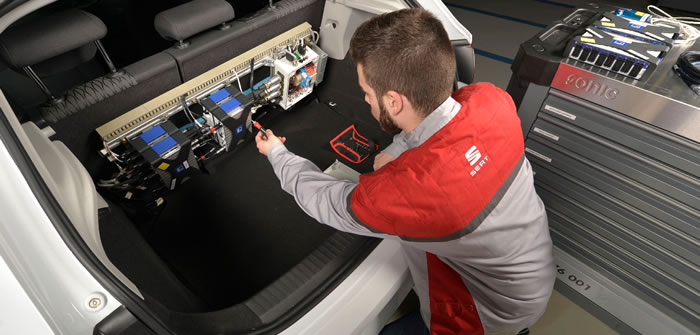
SEAT and Polytechnic University of Catalonia (BarcelonaTech) have jointly developed a unique data acquisition enabling more precise control over instrumented parts and the entire data acquisition process.
SEAT engineers were seeking recently a new data acquisition system fast enough to provide more precise control over instrumented parts and the entire data acquisition process.
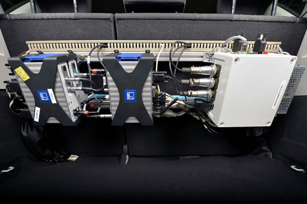
Together with the Polytechnic University of Catalonia (BarcelonaTech), SEAT developed the Autonomous Data AcQuisition (ADAQ) system, comprising QuantumX DAQ modules, catman software and an electronic circuit that supplies power to all devices and for vehicle-pilot interaction.
The following DAQ systems and sensors were used: the QuantumX MX840B universal module; the MX1615B strain gauge module and one CX22B-W datarecorder; thermocouples; accelerometers; strain gauge bridges; displacement sensors; and, in addition, 14 CAN channels and GPS.
Example use case
The system starts up when the vehicle is turned on and performs the following steps:
- Boots up the catman software
- Initiates data storage while the vehicle is on the road
- Stops recording once the car is back at the circuit pit
The ADAQ system transfers data to the SEAT headquarters so analysts can check and analyze the results. The system reports on irregularities and is designed to warn the driver if an error occurs.
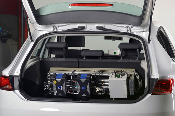
SEAT chose the HBM system for numerous reasons – mainly for its ability to work autonomously and its flexibility. Furthermore the system is small, lightweight and easy to install. It is also designed to work in extreme conditions – for example in vehicle fatigue tests where there is high vibration, g forces, and temperatures.
The catman software was selected due to its many different automation options. The setup includes auto launch of catman, auto loading of the project and automated execution of the first DAQ job. Data files are recorded every 10 minutes. If an unexpected error occurs, the ADAQ system will record up to the moment the error is detected, so no data will be lost.
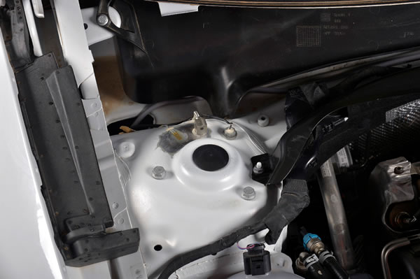
The following filename format is used: XXXYYMMDDHHMMSS, with each letter corresponding to digits for project identification, year, month, day, hour, minute and second. The start and stop acquisition triggers use GPS parameters. For this three parameters must be specified: latitude and longitude coordinates and vehicle speed (greater than 0 to initiate acquisition and equal to 0 when the test is completed).
Control device communicates with driver
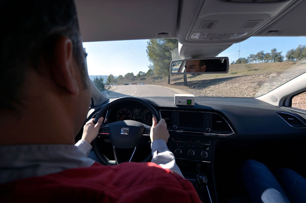
A control device (CD) manages the electronics and distributes power to each module. In addition to the CD, a voltage rectifier and a driver control box have been installed. Thanks to the electronic circuit implemented and the use of CX22B-W digital outputs, four different statuses have been established in order to notify the driver of the different ADAQ phases. This is made possible by two LEDs installed on the vehicle dashboard.
- A permanent red light informs the driver that the devices are booting up and the project is loading when the vehicle is switched on. If the red light comes on during acquisition, an error has occurred, the DAQ process is halted, and the driver must return to the pit stop and report the problem.
- A flashing green light informs the driver that data is being acquired and saved.
- A permanent green light indicates that all devices are ready to initiate data acquisition. The project is waiting for the trigger to start recording data. The driver can leave the box area.
- A flashing red light means that damper temperature is too high.
Once the data has been recorded and saved to the CX22B-W memory card, it is uploaded to the SEAT server for subsequent computer analysis. Thanks to programmed commands and a previously configured AdHoc network, the CX22B-W is able to upload the data autonomously to another laptop in the circuit pit. This laptop sends the data to the SEAT servers overnight. A specific application will subsequently perform the analysis on the preselected channels and generate the required report – all fully autonomously.


